


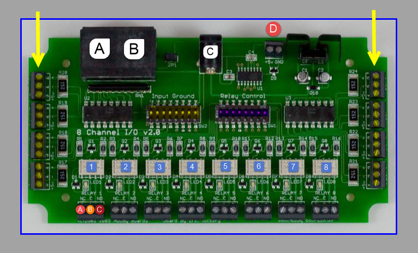
1 wire 8 Channel I/O (8 Relay Version)
Normally open
Normally closed
Common
Realay Swich out put 1 to 8 SPDT relays
4 opto-isolated inputs
4 opto-isolated inputs
External power of 9-24VDC.

C

A

B

D


1-8

A

B
C
Realay Swich outputs 1-8
Realay
Relays are rated for 60W and 62.5VA
which is 2A @ 30VDC or 0.25A @ 250VAC
Dual RJ45 jacks
2-pin screw terminal provides +5v DC
and ground connections
Normally open
Normally closed
LED to indicate relay state
Common
Positive (marked + on the board
+5v (marked +5v on the board
Negative (marked on the board
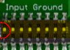
If desired, the relay can be controlled using an external switch, when using the input method ( fig 1a using a push to make switch, when pressed it will activate a relay , you must set a numbered input ground DIP switch (marked Input Ground) must be turned to the on (or up) position when using nonpowered switch devices ).
Using this method do not use the relay number in weather display software as it has been taken and used as an input, you can use a combination of some controlled by weather display using station sensors. Please see the settings in weather display HB1wirereader.
fig 1a

1a
X
Input Terminal SETTINGS for non-powered switching
--------------------------------------------------------------
you must set a numbered input ground DIP switch (marked Input Ground) must be turned to the on (or up) position when using nonpowered switch devices )
Positive (marked + on the board
+5v (marked +5v on the board
Negative (marked on the board
Input Terminal SETTINGS for powered switching
--------------------------------------------------------------
you must set a numbered input ground DIP switch (marked Input Ground) must be turned to the off (or down ) position when using powered switch devices )
Optionally supply +5v to power additional device(s) through the screw terminals marked +5v/GND (4). If used, the power draw should be limited to 100 mA

D
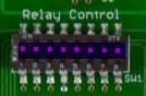
Input Ground control DIP switch 1-8 {ONLY USE IF YOU HAVE A DEVICE YOU WANT TO ACTIVATE THE RELAY MANUALLY, WITHOUT USING WEATHER DISPLAY SOFTWARE
Relay control DIP switch 1-8 (IF THIS MODULE IS BEING CONTROLLED BY WEATHER DISPLAY SOFTWARE RELAY DIP SWITCHES NEED TO BE IN THE ON POSITION, IF YOU HAVE A COMBINATION OF BOTH INPUT DEVICES , WORKING ALONGSIDE WHETHER DISPLAY HAVE THIS RELAY NUMBER SWITCHED OFF SO WHETHER DISPLAY WILL NOT ACTIVATE IT

I connected the relay module to a USB one wire adapter using one of the RJ 45 socket, and plugged in a 12 volt DC power supply . Next I made up (2) 1 wire temperature sensors using DS18S20 these were connected to the second socket RJ 45 on the module board.
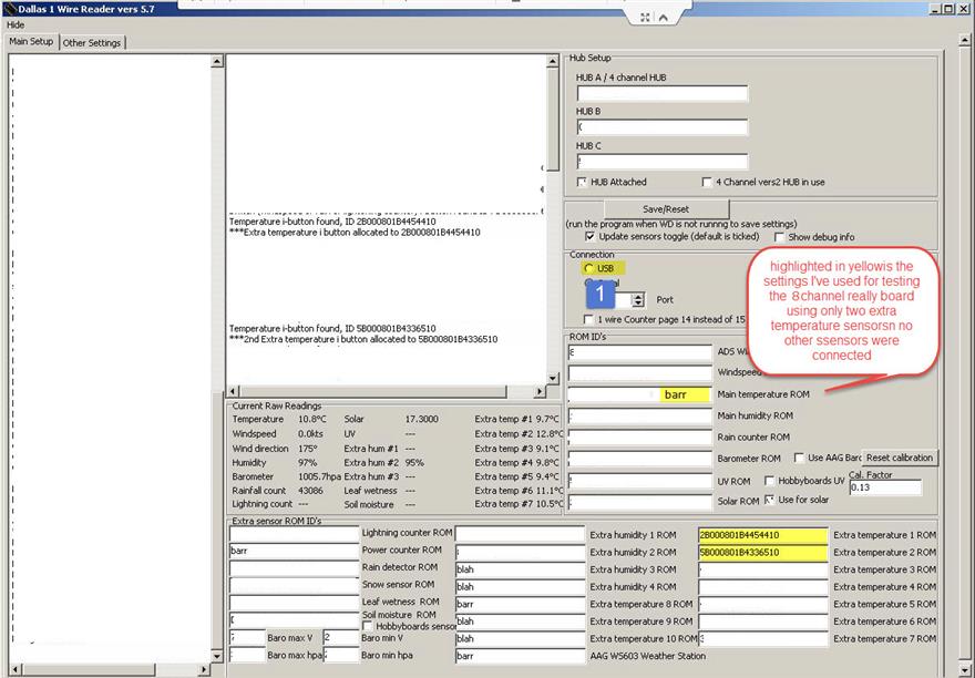
The next stage is to install weather display software , do not run weather display after installing it at this stage, you need to go to the folder and double click on the Dallas1 wire reader .
In this example I'm only using 2 temperature sensors and I want to have these set up as extra temperature sensor. In the Dallas1 wire reader programme make sure you have enabled the correct connection for your device, then click on save/reset, now you will see the programme searching for weather stations sensors when it finds them
it will display ROM numbers ,you may only see 1 Rom number and information , this is because the Dallas 1 wire reader programme has used one of the rom numbers for the main temperature, if this is the case in the box (named main temperature ROM ) type in barr then select save/restart , you may have to close down the Dallas 1 wire reader programme and restart, this time you should be seeing 2 ROM numbers , copy and paste 1 of the ROM numbers in the (extra temperature 1 ROM) box and repeat the process for the other extra temperature 2 ROM. Select save/reset and shutdown,this completes the set up in the Dallas one wire reader for the testing of the relay box using two temperature sensors. Close down the Dallas one wire reader.
Next stage
Start weather display go into ( Control Panel) then click on (com/IP port ) where it says 1 wire com/USB port set up, click on the little box USB port you should see a small tick.
You need to do the same for use the new HB 1 wire reader programme.
Select okay , close whether display down and restart it.
Weather display will start and it will also run automatically the Dallas 1 wire reader followed by the HB 1 wire reader.
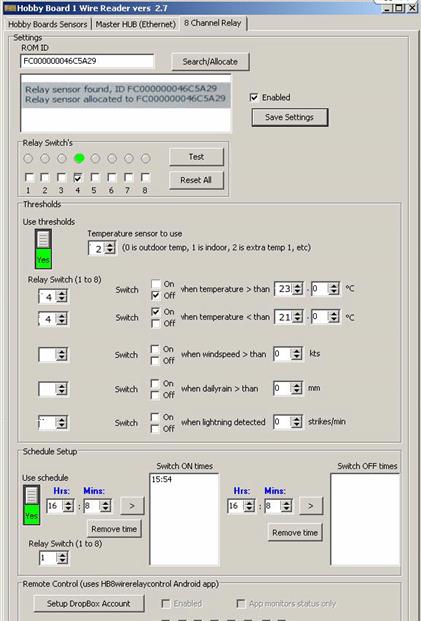
In the taskbar click on the HB 1 wire reader click on the hobby board sensors, click on find sensors ,then go straight to 8 channel relay setting.
Click on search/allocate it will find the ROM number for this device tick enabled and save settings, before going any further do the relay switch test by enabling each number after testing press reset all.
Please see image for the settings I've used in this test in the hobby board one wire reader.
8


Welcome to Weather-Above